Windows Named Pipes Part 4: Taking a Trip Down Static Analysis Lane

Date
Authors
Robert Hawes
Follow Us
Reversing & Exploiting Custom Windows Named Pipe Servers Continued
For the fourth and final blog post of our Windows Named Pipes series, VS-Lab Researchers demonstrate the following information:
-
Static Analysis
- Reversing custom functionality exposed by the named pipe server
- Reversing the named pipe server custom protocol
-
Exploitation
- Walking through a single abuse case targeting given functionality within the named pipe server
These articles are not meant to be an exhaustive reverse engineering tutorial. To keep the material engaging and informative, some code will be covered at a high level to prevent this article from becoming extremely lengthy. If you have not read parts 1-3, skip to those articles using the links below.
Windows Named Pipe Servers Series:
Part 1: The Fundamentals of Windows Named Pipes
Part 2: Analysis of a Vulnerable Microsoft Windows Named Pipe Application
Part 3: Reversing & Exploiting Custom Windows Named Pipe Servers
Static Analysis – Reversing Custom Functionality
We will review the code after the call to CreateNamedPipeW() starting where we left off within part three . Quickly reviewing the graph view of the AAA_namedPipe_startup() function, the red arrow points to the code block where CreateNamedPipeW() is located. This graph can be seen in Figure 1 below.
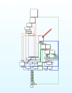
Figure 1 –
CreateNamedPipeW() code block After the valid creation of a named pipe server, the next stage is to identify where the “HANDLE” object associated with the specific \\.\pipe\NinjaReally named pipe is utilized. According to documentation, the next function we should be looking for is ConnectNamedPipe(). This function accepts two arguments, the first is the HANDLE that was returned from CreateNamedPipeW() earlier, and the second argument is potentially either a LPOVERLAPPED, which is a valid pointer to an OVERLAPPED structure, or a null pointer. The presence of ConnectNamedPipe() is seen in Figure 2 below.
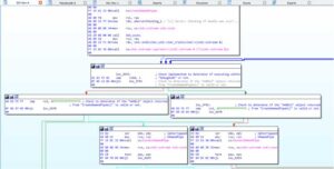
Figure 2 – ConnectNamedPipe Code Path
Reviewing the code within Figure 2, we notice that two different ConnectNamedPipe() function calls exist. The code block on the left is the valid code path that we are after. The code block on the right leads down a path related to debugging and testing code to make sure that the server code is properly implemented.
The ConnectNamedPipe() function will continuously run until either, an error is encountered or a client successfully connects to the named pipe server. Immediately after this call, a check is made to determine if a client successfully connected, and this is implemented by checking the return value from ConnectNamedPipe().
If everything is executed successfully this check will fail because the return value (EAX) does not equal zero, and the code diverts to the next code block at address offset 0x3D90. This code block is responsible for handling the initialization of a local buffer, and it also reads data sent from the client to the named pipe server. The local buffer is initialized with 1023 elements of a 0x00 (null byte) value via a call to memset() at address offset 0x3DDF. Immediately following at address offset 0x3E0E a call to ReadFile() is executed, and the handle to the \\.\pipe\NinjaReally named pipe is passed, and also the buffer initialized via memset() at address offset 0x3DDF, as arguments. An interesting observation to make during the call to ReadFile() is that the nNumberOfBytesToRead argument is one byte less than the total size of the local buffer that holds 1023 bytes. The behavior outlined in this paragraph can be seen in the image below within Figure 3.
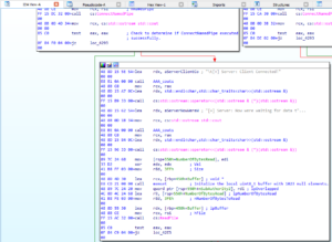
Figure 3 – ReadFile() Code Path
Immediately after the call to ReadFile(), another check is made to determine if the ReadFile() function is executed successfully. If the return value is nonzero, then code execution is diverted successfully to the next code block at address offset 0x3E09, and another check is detected. This check is responsible for ensuring that the value stored within the lpNumberOfBytesRead argument is not null. This is because sometimes, even if the function ReadFile() executes successfully, a chance still exists where ReadFile() reads zero bytes within the provided buffer. This behavior can be seen in Figure 4 below.
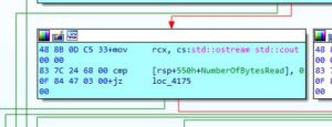
Figure 4 – lpNumberOfBytesRead Check
After that small check, code execution is diverted to the next code block at address offset 0x3E1B. We can quickly identify two print statements at this location and the next interesting instructions begin at address offset 0x3E62. Starting at this location, it is observable that a conditional move if not zero (cmovnz) instruction is executed. The cmovnz instruction relies on the result of the ZF flag value after the previous instruction, cmp (compare), at address offset 0x3E71. The cmp instruction, executes a targeted subtraction of the second operand against the first operand, while altering some of the EFLAGS and, in this specific scenario, the ZF flag. The ZF flag commonly referred to as the Zero Flag is modified during the cmp instruction and is set to 1 if the values being compared are equal, or it is set to 0 if the values are not equal.
In the event of the cmovnz at address offset 0x3E62, a local vector object (var_4B0) has its MyLast and MyFirst fields compared. If they do not match, then a conditional move is executed where the MyLast field is set to the same as the MyFirst field, and code execution will continue to the next interesting code section starting at address offset 0x3E6F. This behavior can be seen in Figure 5 below.
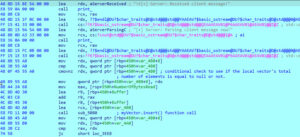
Figure 5 – Local Vector Number of Elements Check
Before the next function call, the few instructions include setting up arguments to be passed to a std::vector insert() member function. The local vector object (var_4B0) will be initialized with the client data recorded within the local variable Buffer from the ReadFile() function call. This behavior can be seen in Figure 6 below.
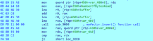
Figure 6 – Local Vector Initialization
After the insert member function call, instructions relating to the std::vector shrink_to_fit() member function are executed at address offset 0x3EE3 and shortly after, the first function of substance is encountered at address offset 0x3EEC. This function call is in relation to the beginning of client data parsing. This behavior can be seen in Figure 7 below.
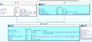
Figure 7 – Entering into first function relating to parsing client data
Upon entering the function sub_2D90, one of the first things we should do is give a quick look at the Graph overview window. This window can provide quick insight into a function such as code density, code flow, error paths, and a general idea of how large or small the function is. This window’s output can be seen in Figure 8 below.
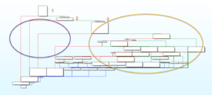
Figure 8 – Graphview Overview of Parsing Function
Reviewing the image above, some noticeable additions were manually added. These are two circles (left and right side) and three numbers. Since this is the start of the client packet parsing, it can be safe to assume that potentially the early error branches that lead to the early return of the function are because of a malformed client packet. These error branches are captured within the circle on the left, and the checks are also captured within the numbers one, two, and three. These code blocks are important because it appears that the majority of all the denser code (within the right circle) is avoided if these checks fail.
Starting at the function prologue some local stack variables and buffers are being initialized to null via call’s to memset() and variables being assigned null via the r14 register. The r14 register is set to null via being previously xor’ed against itself at address offset 0x2DDC. After initializing these local variables and buffers, the first check is made at the address offset 0x2E2F.
The first check is comparing the first BYTE that RAX points to, against, a static value of 0x99. The RAX register appears to come from a dereference of RDI at address offset 0x2E0C. RDI is first initialized by a simple local copy made at address offset 0x2D85, which correlates to RCX which is the vector of client data passed into this function as an argument.
Windows Named Pipes Static Analysis – Introduction to C++ Vector Objects
Understanding and covering the entirety of how all kinds of different C++ containers are operated on within assembly is out of scope for this blog post; however, a quick cover of the memory layout for C++ vectors is approachable. Starting, the vector object will be represented as three pointers within memory.
First Member:
- Pointer to the first element in the Vector
Second Member:
- Pointer to one element past the end of the total initialized elements in the Vector
Third Member:
- Pointer to the end of the total capacity for the Vector
By dereferencing the first pointer within the Vector object, we are essentially operating on the First Member which is a pointer to the first element in the client data packet. This pointer is assigned to RAX at address offset 0x2E0C and shortly after, the first byte in this Vector is compared against 0x99 (within blog post number three in this series, we covered how we determined this was a vector of uint8_t elements). If the check passes then code execution is diverted to the next code block at address offset 0x2E7A; however, if the check fails then the jump is not taken, and the function exits prematurely. This behavior is seen in Figure 9 below.
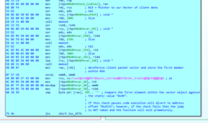
Figure 9 – Checking first element within Vector
Static Analysis – Identifying Usage of Second Member Field within Vector Objects
The next two code blocks appear to be another check; however, reviewing a string referenced by aServerChecking_0; it appears that these two code blocks are in reference to checking the overall length of the client packet. This is seen in Figure 10 below.
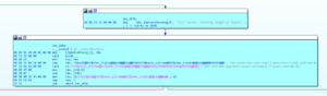
Figure 10 – String Information regarding Client Packet Length Check
At address offset 0x2E9E, another operation involving the local vector is executed. However, instead of focusing on the first member of the vector object, the second member is operated on. As mentioned earlier, the second member is a pointer to one element past the end of total initialized elements within the local vector object. After the second member pointer is moved into RAX a subsequent SUB (subtraction) instruction is executed where the second member (the address of one element past the end of initialized elements within the vector object) is subtracted from the first member (the address of the first element within the vector object). An important note is that this behavior is commonly related to when the member function size() is executed on a vector object. This member function executes the following operation at a high level:
-
Second member – First member =
- total size of elements currently initialized within the vector object
This resulting operation is then stored within RAX, and a CMP instruction is executed utilizing this value at address offset 0x2EAC. If the result of the size() function returns a value either equal to 3 or above, then the check passes, and code execution diverts to address offset 0x2F2E; however, if the check fails, then the function exits prematurely. This can be seen in Figure 11 below.
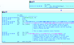
Figure 11 – Checking Size of Client Packet
Static Analysis – First Optimization Encountered
After passing the previous check, the next two code blocks executed are at address offsets 0x2F2E and 0x2F35. With some of the optimizations we have already seen thus far, we are about to encounter another compiler optimization. This optimization will reduce functions down to simple instructions that are inline, and no external function calls are made. The first optimization removes a function call in relation to parsing the first byte within the client data’s local vector. This is observed by reviewing the instructions starting at address offset 0x3013. The first member of our local vector (RDI) is dereferenced and stored within RAX. Then at address offset 0x3024, the first element within our local vector is dereferenced, and the byte is stored within the ESI register via the movzx instruction. Finally, at address offset 0x3047, the register SIL is utilized, which coincides with the usage of a byte because SIL (which is the 8 least significant bits of RSI) is used to represent the byte extracted from the first element of our local vector (at this time is held within a pointer stored in RAX). Utilizing the SIL register, a comparison is made against the static value 1, and if these two values are equal, then the check will pass, and we will continue to the next code block at address offset 0x312F. This behavior can be seen within figure 12 below.
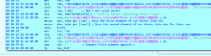
Figure 12 – Function Optimization Detected
The associated source code of the function that this inline assembly represents can be seen in the table below:
parseClientPkt() – Source Code 1 // Extract values from client packet 2 pcpClientType = clientPktVect[0]; 3 pcpClientChallengeNumber = clientPktVect[1]; 4 pcpClientLength = clientPktVect[2]; 5 6 std::cout << "nt[+] Server: Detecting which "Type" of challenge client sent." << std::endl; 7 8 // call Type parsing function. 9 parseTypeField(pcpClientType, pcpClientParsingStruct); 10 switch (pcpClientParsingStruct.typeFieldParsingResponse) {‘ 11 [SNIP] 12 }Reviewing the code snippet above, the direct source code relation within the annotated assembly snippet below is immediately noticeable.
parseClientPkt() - Assembly 1 .text:0000000000003013 mov rax, [rdi] ; RDI = Our Local Vector [SNIP] 2 .text:0000000000003024 movzx esi, byte ptr [rax] ; Move the first element of our Vector into ESI 3 .text:0000000000003027 movzx ebx, byte ptr [rax+1] ; Move the second element of our Vector into ebx for later use [SNIP] 4 .text:0000000000003047 cmp sil, 1 ; Compare first element against 1 5 .text:000000000000304B jz loc_312FReviewing the annotated assembly, it is apparent that within the
parseClientPkt() – Assemblysnippet, lines 1, 2, and 3 directly relate to the lines 2 and 3 within theparseClientPkt() – Source Codesnippet. Next, we will look into the functionparseTypeField()and we will notice that this entire function call was optimized away by the compiler, and a simplecmp sil, 1instruction replaced it. TheparseTypeFile()function source code can be reviewed in the code snippet below.parseTypeField() – Source Code 1 const uint8_t ptfLogicChallenges = 0x01; 2 const uint8_t ptfMemoryCorruptionChallenges = 0x02; 3 4 switch (ptfTypeValue) { 5 case ptfLogicChallenges: 6 std::cout << "tt[!] Server: "TYPE" field value recorded is valid." << std::endl; 7 std::cout << "tt[!] Server: Value is related to "LOGIC" challenges." << std::endl; 8 ptfClientParsingStruct.typeFieldParsingResponse = 0x01; 9 return; 10 default: 11 std::cout << "tt[!] Server: "TYPE" field value recorded is NOT valid." << std::endl; 12 std::cout << "tt[!] Server: Value is not related to any known type." << std::endl; 13 ptfClientParsingStruct.typeFieldParsingResponse = 0x03; 14 return; 15 }So, reviewing the code snippet above, it appears that this function is quite simple as all it does is take in the
ptfTypeValueargument and perform a switch case statement where the only actual value being checked is if theptfTypeValueequalsptfLogicChallengeswhereptfLogicChallengesequals0x01. The otherdefaultcase results in the function simply returning toparseClientPkt(). So, the compiler decided to optimize this entire function call away and inline the function behavior instead.Static Analysis – Second Optimization Encountered
Now, back to the static analysis, if the first byte of the client packet (stored within our local vector) is equal to the numerical value of
0x01then, code execution will divert to the next code block at address offset0x312F.
Upon entering this code block, it is apparent that another compiler optimization has been made. This time, the optimization has removed the function call toparseChallengeFieldLogic().This functions source code can be found within the code snippet below:parseChallengeFieldLogic() – Source Code 1 void parseChallengeFieldLogic(uint8_t pcflChallengeValue, clientParsingStruct& pcflClientParsingStruct) { 2 [SNIP] 3 // Variables 4 const uint8_t pcflWriteFileChallenge = 0x01; 5 const uint8_t pcflDeleteFileChallenge = 0x02; 6 const uint8_t pcflCreateRegistryKeyChallenge = 0x03; 7 const uint8_t pcflCreateRegistryKeyEntryChallenge = 0x04; 8 9 switch (pcflChallengeValue) { 10 case pcflWriteFileChallenge: 11 std::cout << "tt[!] Server: "Challenge" field value recorded is valid." << std::endl; 12 std::cout << "tt[!] Server: Value is related to "Write File" challenge." << std::endl; 13 pcflClientParsingStruct.challengeFieldParsingResponseLogic = 0x01; 14 return; 15 case pcflDeleteFileChallenge: 16 std::cout << "tt[!] Server: "Challenge" field value recorded is valid." << std::endl; 17 std::cout << "tt[!] Server: Value is related to "Delete File" challenge." << std::endl; 18 pcflClientParsingStruct.challengeFieldParsingResponseLogic = 0x02; 19 return; 20 case pcflCreateRegistryKeyChallenge: 21 std::cout << "tt[!] Server: "Challenge" field value recorded is valid." << std::endl; 22 std::cout << "tt[!] Server: Value is related to "Create Registry Key" challenge." << std::endl; 23 pcflClientParsingStruct.challengeFieldParsingResponseLogic = 0x03; 24 return; 25 case pcflCreateRegistryKeyEntryChallenge: 26 std::cout << "tt[!] Server: "Challenge" field value recorded is valid." << std::endl; 27 std::cout << "tt[!] Server: Value is related to "Create Registry Key Entry" challenge." << std::endl; 28 pcflClientParsingStruct.challengeFieldParsingResponseLogic = 0x04; 29 return; 30 default: 31 std::cout << "tt[!] Server: "Challenge" field value recorded is NOT valid." << std::endl; 32 std::cout << "tt[!] Server: Value is related to no known "LOGIC" challenge." << std::endl; 33 pcflClientParsingStruct.challengeFieldParsingResponseLogic = 0x05; 34 return; 35 } 36 }A quick review of this function provides the insight that it is quite similar to the previous function,
parseTypeField(). So, instead of calling into this function to perform a switch statement on the argumentpcflChallengeValue, the compiler chooses to optimize this and utilize the two assembly instructionssubandjzto perform this switch statement. The reason for this is because if we look at the value of the local variables:
-
-
pcflwriteFileChallenge
- Value ->
0x01
- Value ->
-
pcflDeleteFileChallenge
- Value ->
0x02
- Value ->
-
pcflCreateRegistryKeyChallenge
- Value ->
0x03
- Value ->
-
pcflCreateRegistryKeyEntryChallenge
- Value ->
0x04>
- Value ->
-
By simply performing a subtraction of the user-supplied byte (pcflChallengeValue) against these four different local variables used as cases for the switch statement, the sub instruction will only set the ZF flag to 1 if the result of the subtraction is zero. So, by utilizing the conditional jump if zero (jz) instruction with the subtraction (sub) instruction, the compiler can create a simulated switch statement within the assembly.
So, reviewing the check within the assembly at address offset 0x3196, we can trace ECX to the previous instruction at address offset 0x3196, where a mov instruction is executed, and ECX is populated with the value that the EBX register currently holds. By tracing where EBX comes from, we will land at the address offset 0x3027. In this previously mentioned address, at this location, a movzx instruction is executed with the EBX register as the destination, and byte ptr [rax+1] as the source. This is important because the RAX register is the first member of our local vector object, which points to the first element within our vector, and by incrementing the pointer by the numerical value of 0x01, we will be reading the second byte in the client packet (local vector).
So, at this moment, we understand that the client packet is stored within a local vector of uint8_t elements and the first two elements within the vector are:
Client Packet -> [0x00: -> Type of Challenge (Logic or Memory Corruption)]
Client Packet+1 -> [0x00: -> Type of Logic Challenge]
Now, returning to the beginning of the optimized switch statement at address offset 0x3193, we subtract the second element within our client packet (which is a single byte) against the value of 1 and storing the results in ECX. The switch statement optimization can be seen in the table below, where four condition jumps are encountered in sequence.
Optimized Switch Statement - Assembly .text:0000000000003191 mov ecx, ebx .text:0000000000003193 sub ecx, 1 .text:0000000000003196 jz loc_37FA .text:000000000000319C sub ecx, 1 .text:000000000000319F jz loc_3509 .text:00000000000031A5 sub ecx, 1 .text:00000000000031A8 jz loc_33CC .text:00000000000031AE cmp ecx, 1 .text:00000000000031B1 mov rcx, cs:?cout@std@@3V?$basic_ostream@DU?$char_traits@D@std@@@1@A ; a1 .text:00000000000031B8 jz loc_329BWe noted that four values, which were
0x01,0x02,0x03, and0x04, were all utilized as cases within the switch statement and the switch statement executed in order from0x01to0x04.This is important because we notice in the assembly in the snippet above that if the client provided value was
0x04, the first conditional jump would fail, andECXwould equal0x03. Then the second conditional jump would also fail, causingECXto equal0x02, then the third conditional jump would also fail andECXwould finally equal0x01. The final conditional jump is executed using acmp(comparison) based conditional jump if equal (jz).With a hard-coded value of
0x01on the final comparison, the check will pass if the provided value is0x04. Otherwise, if it is above0x04code execution will divert to an error path, and the application will terminate. If the value is below0x04then the check would execute one of the previous conditional jumps instead.If we wanted to verify that only four possible paths exist, we can look at the code after the final check and see what would happen if the conditional jump failed and the value of
ECXwas not0x01. You can see this by reviewing the code block at address offset0x31BE. This function performs what appears to be some error logging, and finally, it moves the value of0x03intoALand jumps to the next code block at address offset0x397A.Instead of reviewing this code path further, reviewing the graph outline below in Figure 13 will provide adequate information about how this code path leads directly to this function returning.
Figure 13 – Error Code PathReviewing the image above, we see an error path highlighted in green. This is the direct path that is executed as the
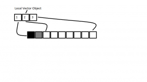
defaultpath within the switch case statement that correlates to theparseChallengeFieldType()function within the source code. However, in this case, this is the assembly. This is important because if no source code were available this would provide valuable information about the second byte accepted values within the client packet. With this new information about the accepted values, one would create a mental image of the potential values such as in the image below.
Figure 14 – Visualization of Vector ObjectReviewing the image above, it is noticeable that the first three squares labeled
1,2, and3represent our local vector’s member fields in memory. These member fields are all pointers and were discussed earlier in this blog post. By reviewing the previous information about the optimization and switch case layout for theparseChallengeFiledType()function, we can deduce that the four valid values for the second byte within the client packet are:
- 0x01
- 0x02
- 0x03
- 0x04
Any other value provided will result in the early termination of this function, and no further parsing of the client packet within the named pipe server will happen. This same technique we used to derive the four total possible valid values for the second byte within the protocol can also be applied to the first byte. Reviewing the image below will showcase this new information.
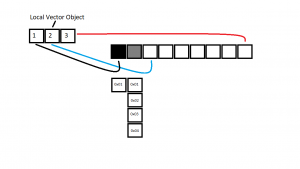
Figure 15 – Updated Valid Protocol Values
Now, back to the conditional check at address offset 0x3193, we are going to assume that the client sent a value of 0x01 and this conditional check passed, and we enter the next code block at address offset 0x37FA.
This is an interesting code block because, unlike the others so far, this is the first time we will be entering a function that was not optimized away. This can be seen by the function call at address offset 0x384B. Looking at the arguments being passed, we notice a stack pointer, var_c80, is being passed via RCX, the pointer to our local vector object is being passed via RDX, and a null byte via the r8d register. This can be seen in Figure 16 below.
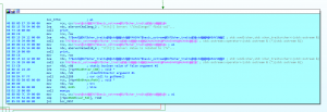
Figure 16 – getName() function call
Static Analysis – Reversing Structures
Reversing Structures – Introduction
Reviewing the instructions immediately after the function call to sub_12E0(), it is apparent that a large array of some data type is being populated via a call to the function memcpy(). The source argument is RAX, which in this case is the return value from “code>sub_12E0(), the destination argument is a pointer to some type of array located on the stack, and finally, the number of bytes being copied is ”0x624”.
Before continuing further, we need to review some documentation that Microsoft provides regarding how functions with a return type of a structure are treated since the compiled binary was created using MSVC.
MSDN – Documentation (x64 Calling Convention | Return Values) Return values A scalar return value that can fit into 64 bits, including the __m64 type, is returned through RAX. Non-scalar types including floats, doubles, and vector types such as __m128, __m128i, __m128d are returned in XMM0. The state of unused bits in the value returned in RAX or XMM0 is undefined. User-defined types can be returned by value from global functions and static member functions. To return a user-defined type by value in RAX, it must have a length of 1, 2, 4, 8, 16, 32, or 64 bits. It must also have no user-defined constructor, destructor, or copy assignment operator. It can have no private or protected non-static data members, and no non-static data members of reference type. It can't have base classes or virtual functions. And, it can only have data members that also meet these requirements. (This definition is essentially the same as a C++03 POD type. Because the definition has changed in the C++11 standard, we don't recommend using std::is_pod for this test.) Otherwise, the caller must allocate memory for the return value and pass a pointer to it as the first argument. The remaining arguments are then shifted one argument to the right. The same pointer must be returned by the callee in RAX. These examples show how parameters and return values are passed for functions with the specified declarations: struct Struct1 { int j, k, l; // Struct1 exceeds 64 bits. }; Struct1 func3(int a, double b, int c, float d); // Caller allocates memory for Struct1 returned and passes pointer in RCX, // a in RDX, b in XMM2, c in R9, d pushed on the stack; // callee returns pointer to Struct1 result in RAX.So, using the knowledge that functions returning a structure that exceeds 64 bits in size, place the responsibility of creating the structure and allocating adequate memory on the
Callerand theCallerpasses the structure viaRCXbefore the normal arguments passed to the function. We can observe this behavior happening before the call to thesub_12E0()function and can be reviewed by the image Figure 16.Armed with this knowledge, we will embark on attempting to reverse an undocumented structure statically and start understanding what the potential members are and what their associated data types are.The technique used here will be purely static analysis; one could use dynamic analysis to perform research into reversing an undocumented structure; however, this entire post is focused on a static analysis approach.
It is also important to note that accurately reversing structures is dependent upon one’s knowledge of how the compiler compiles source code using different compiler flags and optimization levels; these techniques can vary between compilers and the optimization levels. While reversing undocumented structures; understanding how higher-level concepts translate to assembly is also important. I will do my best to cover as much as possible; however, this is not an entire break down and is more of an introduction to reversing structures in this blog post section.
Reversing Structures – What is VAR_C80?
If we look at the stack for the function
sub_2D90()using theStackwindow page withinIDA Pro, it is observable that this function holds two large local variables. This can be seen in the table below.sub_2D90 – Stack -0000000000000CA0 ; D/A/* : change type (data/ascii/array) -0000000000000CA0 ; N : rename -0000000000000CA0 ; U : undefine -0000000000000CA0 ; Use data definition commands to create local variables and function arguments. -0000000000000CA0 ; Two special fields " r" and " s" represent return address and saved registers. -0000000000000CA0 ; Frame size: CA0; Saved regs: 8; Purge: 0 -0000000000000CA0 ; -0000000000000CA0 -0000000000000CA0 db ? ; undefined -0000000000000C9F db ? ; undefined [SNIP] -0000000000000C80 var_C80 db ? -0000000000000C7F db ? ; undefined -0000000000000C7E db ? ; undefined -0000000000000C7D db ? ; undefined [SNIP] -0000000000000651 db ? ; undefined -0000000000000650 pszPath db 256 dup(?) ; string(C) -0000000000000550 var_550 dd ? -000000000000054C var_54C dd ? -0000000000000548 db ? ; undefined -0000000000000547 db ? ; undefined -0000000000000546 db ? ; undefined [SNIP] -0000000000000354 var_354 dq ? -000000000000034C var_34C dd ? -0000000000000348 var_348 db ? [SNIP] -0000000000000048 var_48 dq ? -0000000000000040 var_40 xmmword ? -0000000000000030 var_30 dd ? -000000000000002C db ? ; undefined -000000000000002B db ? ; undefined -000000000000002A db ? ; undefined -0000000000000029 db ? ; undefined -0000000000000028 db ? ; undefined -0000000000000027 db ? ; undefined -0000000000000026 db ? ; undefined -0000000000000025 db ? ; undefined -0000000000000024 db ? ; undefined -0000000000000023 db ? ; undefined -0000000000000022 db ? ; undefined -0000000000000021 db ? ; undefined -0000000000000020 Stack_Cookiez dq ? -0000000000000018 db ? ; undefined -0000000000000017 db ? ; undefined -0000000000000016 db ? ; undefined -0000000000000015 db ? ; undefined -0000000000000014 db ? ; undefined -0000000000000013 db ? ; undefined -0000000000000012 db ? ; undefined -0000000000000011 db ? ; undefined -0000000000000010 db ? ; undefined -000000000000000F db ? ; undefined -000000000000000E db ? ; undefined -000000000000000D db ? ; undefined -000000000000000C db ? ; undefined -000000000000000B db ? ; undefined -000000000000000A db ? ; undefined -0000000000000009 db ? ; undefined -0000000000000008 db ? ; undefined -0000000000000007 db ? ; undefined -0000000000000006 db ? ; undefined -0000000000000005 db ? ; undefined -0000000000000004 db ? ; undefined -0000000000000003 db ? ; undefined -0000000000000002 db ? ; undefined -0000000000000001 db ? ; undefined +0000000000000000 s db 8 dup(?) +0000000000000008 r db 8 dup(?) +0000000000000010 db ? ; undefined +0000000000000011 db ? ; undefined +0000000000000012 db ? ; undefined +0000000000000013 db ? ; undefined +0000000000000014 db ? ; undefined +0000000000000015 db ? ; undefined +0000000000000016 db ? ; undefined +0000000000000017 db ? ; undefined +0000000000000018 arg_8 dq ? +0000000000000020 arg_10 dq ? +0000000000000028 +0000000000000028 ; end of stack variablesReviewing the table above, the two large local variables are referred to as
VAR_C80andpszPath.
Now, at this exact moment, it is hard to tell exactly what data type these variables are or even if they are structures to begin with. At this time, all we can tell is that starting at offset0xC80is a local variable, and the next local variable on the stack is0x630bytes away, and that ispszPathat offset0x650. For simplicity we can assume right now thatVAR_C80is some array that holds0x630bytes.Reversing Structures – Navigating to the Structures Window
Knowing that the
VAR_C80local variable could potentially be a structure of0x630bytes in length, we will create a new structure withinIDA Proand assign this new structure to the local variableVAR_C80.
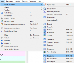
To create a new structure, first, open theStructureswindow withinIDA Pro. This is accomplished either through navigating to theView-> “code>Open subviews menu option and manually selecting theStructuresoption, or executing the hotkey combinationShift + F9. This behavior can be seen in Figure 17 below.
Figure 17 – Opening the Structures WindowAfter opening the
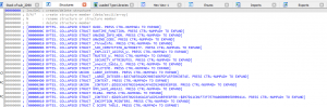
Structureswindow, we will be presented with the current structures thatIDA Prohas registered. This can be seen in figure 18 below.
Figure 18 – IDA Pro Structures WindowReviewing the image above, the important information is within the open and closed brackets ([]), and we will use the
_FILTTIMEstructure as an example for reading.
Starting off, the first row/element within the brackets is an integer, which displays the structure’s total size. The next important row/element is after theCOLLAPSED STRUCT/UNIONrow and this row/element shows the structure’s name. In this event, it easy to tell that the_FILETIMEstructure is only 0x08 bytes in length.Reversing Structures – Creating a New Structure
After navigating to the
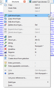
Structureswindow, we can create a new structure by either navigating to the whitespace at the bottom of the structure list with our cursor andright clickingto bring up a sub menu where we can select the menu optionAdd struct type…or we can hit theInsert(shorthand named INS) hot key as demonstrated in the figure below.
Figure 19 – Add New Structure MenuAfter selecting the
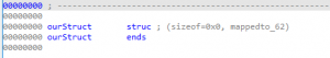
Add struct type…menu option, another new window will appear calledcreate structure/union. Within this window, we will select thetextwithin thetext boxassociated withStructure Nameand call this new structureourStruct. Then select the optionok, and a new structure will now be created within theStructureswindow. This behavior can be seen in the image below.
Figure 20 – Newly Created StructureourStructReversing Structures – Creating New Member Fields within ourStruct
After creating the initial structure, the next step is to modify our structure and add member fields. As mentioned earlier within the
What is VAR_C80sub section, theVAR_C80local structure/variable is potentially around0x630bytes in length. Knowing the potential size, we will start by adding a blank array of0x630bytes within theourStructstructure.To accomplish this, select the
ourStructstructure (make sure that it is highlighted yellow) andright-clickwith your mouse. This will bring up a new window full of menu options. These options can be seen in the image below.
Figure 21 – Creating New Array Member”Reviewing Figure 21 above, the options such as adding new member are:
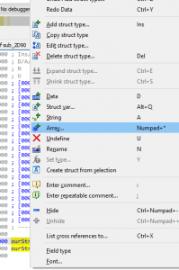
- Data – D
- String – A
- Array – Numpad+* (Shift+8)
By selecting the Array… menu option, a new window called convert to array will appear. We will want to select the Array Size field and modify it to be “code>0x630 (1,584) elements. Then select Ok at the bottom. This can be seen in the figure below.
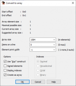
Figure 22 – Modifying Number of Array Elements”
After selecting Ok, the ourStruct structure within the Structures window, will be modified to reflect the new addition of the first member field within the structure as seen in the image below.
Figure 23 – Newly Created Member Field”
Reversing Structures – Modifying VAR_C80 to be of ourStruct data type
After the creation of the ourStruct structure within the Structures window within IDA Pro. The next step is to modify the local variable var_C80 within the stack of the sub_2D90 function.
To perform this operation, navigate to the start of the sub_2D90 function within either text or graph view (or find a reference to var_C80 within the assembly of the function) and locate var_C80 within the stack information, as seen in the image below.
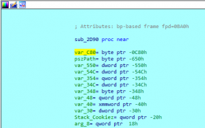
Figure 24 – Local Reference of var_C80 on the stack
After finding var_C80, double click with the left mouse button, and IDA Pro will present the associated stack within a new window called stack of , as seen in the image below.
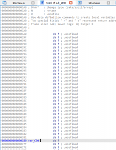
Figure 25 – Reviewing sub_2D90 stack
Next, highlight var_C80 with the mouse pointer and right click. After that, a new window pop-up will appear and select the menu option Struct var… (or execute the hot-key combination, Alt+Q), as seen in the image below.
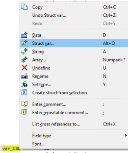
Figure 26 – Modifying var_C80 into a Structure”
Upon selecting the Struct var… menu option, a new window will appear, titled Choose a structure (not the current!). Within this window, we will see a list of available structures within our IDA Pro session. At the bottom, we notice the ourStruct structure we created earlier. Please select this option, then click the Ok icon, as seen in the image below.
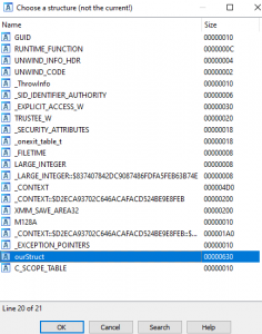
Figure 27 – Selecting
ourStructAfter selecting OK, the Choose a structure window will disappear, and the var_C80 variable within the sub_2D90 stack window will be modified so that instead of a continuous array of single bytes, it will instead now be represented as an ourStruct structure. This behavior can be seen in the image below.
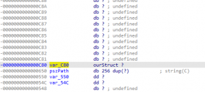
Figure 28 – Modified var_C80 variable”
Now that we have successfully modified var_C80 to be represented as an ourStruct structure, any modifications we make to the ourStruct structure will be represented in the disassembly where var_C80 member fields may be utilized.
Reversing Structures – Where is VAR_C80 Utilized?
After identifying VAR_C80 on the stack and getting a rough idea of potentially how large of an array it is, the next step is finding where it is first referenced or utilized. The reason for this is because at this moment, all we see is a large single byte array of 0x630 (0xC80 – 0x650) bytes in length. Without the context of how this local structure/variable is being utilized, we will never know the structure’s true layout and its members fields, and their associated data types.
To start, we will cross reference the VAR_C80 variable and see all locations where it’s either being written to or maybe used as an argument within the sub_2D90() function. Through navigating to the start of the function within IDA Pro’s IDA View window, select the variable VAR_C80, and while selected, press the hotkey x on your keyboard. This will open the xrefs to window. This behavior can be seen in the image below.
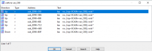
Figure 29 – Reviewing
var_C80 XrefsReviewing the image above, we identify seven locations within the sub_2D90 function where var_C80 is passed presumably as an argument to a function via a LEA instruction where the destination operand is RCX. This correlates to the information we covered earlier within the Reversing Structures – Introduction section.
It is important to note that although each of these cross-references depicts var_C80 as being utilized as an argument being passed to a function, it is possible that var_C80 could be passed to another local variable (operated on by being stored within another register) and operations performed on that variable instead. This information is important because, we are trying to understand HOW the structures internal member fields are being utilized. Without source code or symbols, structures are commonly treated as just arrays of bytes when reviewing the structures within disassemblers. Depending on how each disassembler performs their post-analysis, they might be able to provide insight into internal member fields.
Looking at an example of usage at address sub_2D90+AB3, we will notice that all the other cross references share an exact same template (template in this manner is being used generically and refers to the overall layout of the instructions surrounding this address).
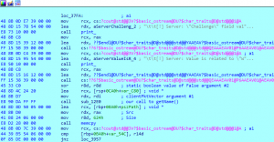
Figure 30 – Generic Usage of
var_C80Reviewing the image above, we notice a similar pattern between this single use case and the other six use cases. The pattern is that we have a function call where var_C80 is passed via RCX, then immediately after the function call, a memcpy() call is made where the return value is copied into the local variable pszPath, of a total size of 0x624 bytes.
Reversing Structures – Why such little usage of VAR_C80 within sub_2D90
An invested reader might have noticed that we recorded little usage of the var_C80 variable within the sub_2D90 function. This can be for many reasons; however, in this example the reason relates directly to the information covered within the Reversing Structures – Introduction section; regarding how MSVC handles functions that return a structure value larger than 64bits. We should look within the functions being called where var_C80 is being passed as an argument with this information.
Reversing Structures – Digging into sub_12E0
Although we are diving into functionality relating to reversing structures within these sections of the blog post, we will also be reversing sub_12E0 in its entirety as an example.
Now, by performing the cross-reference check within the Where is VAR_C80 Utilized? section of this blog post, it is apparent that two functions exist where var_C80 is being passed as an argument. These two functions are, sub_12E0 and sub_1760. Starting at the address offset 0x384B, a function call to sub_12E0 is executed. Upon entering this function, we will be tracing usage of RCX, which correlates to var_C80, RDX, which correlates to our local vector object (client packet), and r8 within the caller function (sub_2D90).
Digging into sub_12E0 – Initial Impressions
Upon entering the sub_12E0 function, the first operation we will perform is to glance at the overall layout of the function by reviewing the graph seen in the image below.
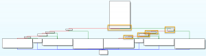
Figure 31 – sub_12E0 Graph
Initial observations of the function, provide insight such as:
- Two potential code paths that are similar in behavior
- Total of five checks are implemented per path
- The overall function is not all that complicated upon first glance
With these observations made the first step is to begin analysis with the first code block of the sub_12E0 function.
Digging into sub_12E0 – First Code Block Overview
Reviewing the first code block at address offset 0x12E0, the first few instructions are related to the function prologue. Next we notice some calls to the memset() function, then finally a check is made against the static value of 0x01. This can all be seen in the image below.
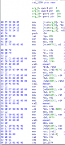
Figure 32 – sub_12E0’s initial code block
Digging into sub_12E0 – Identifying the First Check
Reviewing the image above, at address offset 0x12FC, a mov instruction is executed, and the value that r8d holds is placed into the EBX register. Then at the end of this code block at address offset 0x139D, EBX is compared against the static value 0x01 and if the two values do not equal each other, the check passes; however, if they do equal each other, the check fails.
The r8d register coincides with the third argument passed to the sub_12E0 function within the caller function at address offset 0x3840, where it is nulled out, as seen in the table below.
Sub_29D0 – r8d argument .text:0000000000003840 xor r8d, r8d ; static boolean value of False argument #2 .text:0000000000003843 lea rcx, [rsp+20h] ; void * .text:0000000000003848 mov rdx, rdi ; clientPktVector argument #1 .text:000000000000384B call sub_12E0 ; our call to getName()Digging into sub_12E0 – First initialization to our structure
After the assignment of
r8dtoEBX, the next instruction that follows immediately is an assignment for alignment purposes (we will verify the behavior later in this section), at address offset0x12FFas seen in the table below.RCX (var_C80)+0xFF Alignment .text:00000000000012FF mov [rcx+0FFh], alIt is important to note that structures in the assembly are treated as an array of bytes, so with
RCXequaling the very first byte in our array, if we wish to access a member atxoffset, we must add that value to the base address of the structure. An example could be:
- RCX Base Address of Structure = 0x00004100
- We wish to access a char pointer located at offset 0x22 into the structure
- We would operate on RCX+0x22
- Char Pointer Address = 0x00004122
Updating ‘ourStruct’ Structure
After seeing that at offset 0xFF into our structure, a null byte is initialized, we can go ahead and update ‘ourStruct’ structure with this new information. To update ourStruct, please select the menu option View -> Open subviews -> Structures, this will open up the Structures window within IDA Pro.
Upon navigating to the Structures window, we will be looking at modifying the member fields within our ourStruct structure. To update the members field, please highlight the first field field_0 and right click, then select Array…. This should open a new window called Convert to array as seen in the image below.
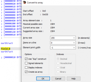
Figure 33 – Modifying ourStruct Structure
Reviewing the information above, we are modifying the first array to be of size 0xFF (255) because we know that at offset 0xFF into the structure, we initialize a value to Null at address offset 0x12FF within the sub_12E0 function. The new ourStruct structure will represent a single array of size 0xFF as seen in the image below.
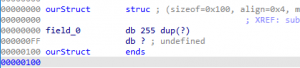
Figure 34 – ourStruct Structure after update of First Field
Reviewing the image above, we notice that the ourStruct structure is no longer 0x630 bytes in length; however, it is now 0x100 in total length.
The total length has been modified because we operated on that single member field, and at the beginning starting out, we are not aware of what each member field really is. So, we created a single member field that was of 0x630 bytes in length. However, now that we are gaining some further context of the type of data within the structure, we start adding and manipulating the member fields within as we gain more understanding of what each member field may represent.
Fixing member fields of ourStruct Structure
Now, after modifying this structure’s single member field, we must add the remaining 0x531 bytes starting at offset 0x100. To create a member field at that offset, please highlight offset 0x100, then right click and select the option Array… as seen in the image below.
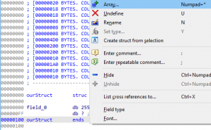
Figure 35 – Creating Second Member Field within
ourStructThis will open the Convert to array window, and we will create a second member field with a total size of 0x531 (1,329) as seen in the image below.
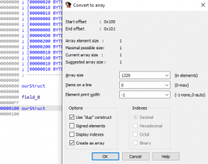
Figure 36 – Second Member Field Size within ourStruct
After selecting OK, we will notice that the newly create byte array starting at offset 0x100 is of size 0x531; however, a new issue has appeared. The total size of ourStruct structure is now larger than the original 0x630 bytes. So, we need to account for the 0x04 byte alignment we manually added earlier to ourStruct and modify the newly added member field field_100 to be of size 0x52D (1,325), and this will fix the alignment issue. We are using an alignment of 0x04 because Visual Studio 2019 uses a default structure member alignment option within the project’s properties. If you wish to modify the alignment used manually, you can directly modify this option, which correlates to the flag Zp.
Now, the newly created ourStruct structure should be like the image below.
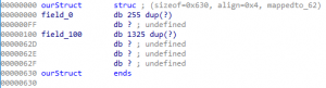
Figure 37 – Second Member Field Added within
ourStructRecap of ourStruct structure insights
At this moment, the ourStruct structure is starting to show some interesting values. We have two large single byte arrays where one is of size 0xFF and another is 0x52D. We also know that at offset 0xFF into ourStruct, we have a single byte of value null, and this appears to be related to potential alignment behavior executed by the compiler via the default value of the Zp compiler flag. Right now, we can take few guesses as to what field_0 may be; however, to verify this assumption, we will have to investigate how this member field is operated on within the binary itself. This concept applies to both fields within our structure.
Digging into sub_12E0 – Local Vector & First memset()
So, at this point, we know that at offset 0xFF into our structure (var_C80) within RCX, a value is initialized with a null value. After this, at address offset 0x1305, our local vector object (client packet) is placed into the RSI register. The local vector object is only used once within the first code block, which is near the end, starting at address offset 0x1393.
The reason we know this is our vector object is because RDX is assigned via RDI at address 0x3848 within the caller function, sub_2D90. The RDI register at that moment holds our vector object (client packet).
Next, we encounter the first memset() function, where 0x1F4 bytes with the value of null are written, starting at offset 0x108 into our structure (var_C80) within RCX. This behavior can be seen in the table below.
First Memset() – var_C80 .text:000000000000130B xor edx, edx ; Val .text:000000000000130D add rcx, 108h ; void * .text:0000000000001314 mov r8d, 1F4h ; Size .text:000000000000131A call memsetLocal Vector & First
memset()Looking at this first
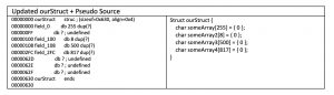
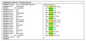
memset()function call, it is apparent that at offset0x100, we have some type of value(s) that take up 8 bytes withinourStructstructure. At offset0x108, we initialize a larger member field of size0x1F4(500) bytes. You can see a general layout of the new information in the table below, where the associated pseudo source is also available as a reference.
Example 1 – UpdatedourStruct+ Pseudo SourceAt this moment, we are not exactly sure what any of these member fields are or if these are even the right data types. A common theme so far is that we are modifying the structure as we go, and as we uncover my information about HOW the member fields are utilized, we will begin to understand what each member field is and its purpose.
Digging into sub_12E0 – Second
memset()& Further initializationsThe second
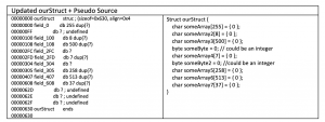
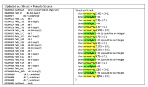
memset()function call is at address offset0x133F; however, unlike the previous section, we will also address two more single byte initialization within theourStructstructure. The first two single byte initialization’s are at address offset’s0x2FCand0x304. Thememset()function call is for0x201bytes with a value ofnull, starting at offset0x407intoourStructstructure. The assembly responsible for this behavior can be seen in the table below.Second Memset & Initializations .text:000000000000131F xor r14d, r14d .text:0000000000001322 lea rcx, [rdi+407h] ; void * .text:0000000000001329 xor edx, edx ; Val .text:000000000000132B mov [rdi+2FCh], r14 ; .text:0000000000001332 mov r8d, 201h ; Size .text:0000000000001338 mov [rdi+304h], r14d .text:000000000000133F call memset ;These assembly instructions modify our
ourStructstructure in a specific manner and their results can be seen in the table below with the updated structure.
Example 2 – UpdatedourStruct+ Pseudo SourceNow, reviewing and maintaining a mental image of our structure’s layout would be difficult; so, I suggest keeping a notepad available to keep track of the initializations so far. It is easy to become confused during initial reversing when first starting; after a while, one will become more efficient though.
Digging into sub_12E0 – Third
memset& further initializationsEntering the third
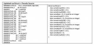
memset()function call at address offset0x1364, three single byte assignments are executed using ther14register, which has previously beenxor’edtonullat address offset0x131F. Along with these three singlenullbyte initializations, thememset()function call creates a0xFF(255) byte array starting at offset0x00ofourStructstructure. The assembly responsible for this behavior can be seen in the table below.Third Memset & Initializations .text:0000000000001344 xor edx, edx ; Val .text:0000000000001346 mov [rdi+608h], r14 .text:000000000000134D mov r8d, 0FFh ; Size .text:0000000000001353 mov [rdi+614h], r14 .text:000000000000135A mov rcx, rdi ; void * .text:000000000000135D mov [rdi+61Ch], r14 .text:0000000000001364 call memsetThese assembly instructions modify our
ourStructstructure in a specific manner, and you can view their results in the table below with the updated structure.
Example 3 – UpdatedourStruct+ Pseudo SourceNow, at this moment, the pseudo code is becoming even more convoluted; however, I promise, starting out, it is important to do this and document each change manually within the structure. An important note here is that these single byte initializations could be exactly that, a single byte; however, they could also be an integer or a pointer. At this exact moment, we have no context of how these fields are utilized, so we have no real understanding if they are a byte, integer, or pointer.
Digging into sub_12E0 – Final
memset& InitializationsEntering the last
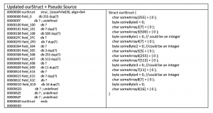
memset()function call within the first code block, executed at address offset0x1380, it is observed that an array of size0xFFwith a value ofnullis initialized at offset0x308into theourStructstructure. Along with thememset, another single byte initialization occurs where at offset0x100intoourStructstructure, anullvalue is written via theEAXregister. The assembly responsible for this behavior can be seen in the table below.Final Memset & Initializations .text:0000000000001369 xor eax, eax .text:000000000000136B lea rcx, [rdi+308h] ; void * .text:0000000000001372 xor edx, edx ; Val .text:0000000000001374 mov [rdi+100h], eax .text:000000000000137A mov r8d, 0FFh ; Size .text:0000000000001380 call memsetThese assembly instructions modify our
ourStructstructure in a specific manner and their results can be seen in the table below with the updated structure.
Example 4 – UpdatedourStruct+ Pseudo SourceDigging into sub_12E0 – Final Initialization within
ourStructin First Code BlockAfter the last
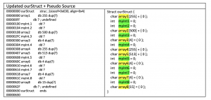
memset()function call, two more members are initialized withinourStructstructure. These fields are at offsets0x610and0x104. The initialization happens via axorinstruction executed at address offset0x1385where theEAXregistered isxor’edagainst itself, resulting in anullvalue. The assembly responsible for this behavior can be seen in the table below.Final Initializations .text:0000000000001385 xor eax, eax .text:0000000000001387 mov [rdi+610h], eax .text:000000000000138D mov [rdi+104h], eaxThese assembly instructions modify our
ourStructstructure in a specific manner and their results can be seen in the table below with the updated structure.
Example 5 – UpdatedourStruct+ Pseudo SourceReviewing the newly created structure within the table above, it is observable that it is still hard to read and decipher. Now, we have all the single byte initializations set to a single byte and every other potential value assigned to a byte array. For simplicity of reading, we will convert every single byte member field into a four-byte integer data type. This newly created structure can be seen in the table below.
Example 6 – UpdatedourStruct+ Pseudo SourceAfter some modifications and renaming of member fields within the
ourStructstructure, we are finally starting to reach a point where readability of our structure is increasing. We are still a long way from a complete 1:1 source and this approach may be tedious, but it is effective.Digging into sub_12E0 – A quick look at compiler optimizations and associated behavior
Before we dive into why we initially set all those single byte initializations to a data type of an
INT, lets talk about compiler optimizations and its behavior. This section is short and is not an entire in-depth review of compiler internals; however, it should provide readers with adequate initial guidance in the right direction. As mentioned earlier in this blog post, the compiler we are basing our analysis on is MSVC.Starting out, we must understand that compilers can compile source code into machine code using multiple different levels of optimizations. Each different compiler will behave slightly different when it comes to compiling source into machine code. Along with different compilers having different behavior, different compiler versions may also exhibit slightly different behavior.
Understanding that everything is compiler version dependent (to some degree), we will utilize the online tool
Compiler Explorercreated byMat Godbolt. We will review the disassembly of the associated compiled source code in the table below.Generic Example Source Code // Type your code here, or load an example. #include <windows.h>; #include <stdio.h> struct dataType { BYTE wow = 0; short wow2 = 0; int wow3 = 0; }; int main() { struct dataType dog = {}; dog.wow = 1; dog.wow2 = 2; dog.wow3 = 4; printf("Dog.wow = %d", dog.wow2); return 1; }We will utilize the
MSVCcompiler and specify a manual compiler flag ofOd, to disable all optimization levels. The reason for this is because, if we leave it at default (O2), all the important aspects for learning are optimized away and all we will see is aprintf()function call where the second argument is a hardcoded value of0x02.Now, reviewing the source code above, we have the
main()function defined where a local struct calleddog, based on thedataTypestructure, is created. ThedataTypestructure has three different member fields, each with a data type ofBYTE,short, andint. Withinmain(), the member fields of thedogstructure are initialized with1,2, and4.According to the MSDN documentation, each data type has a specified size (width), meaning that a
BYTEdata type is represented as a single BYTEcommonly represented as either _int8 or unsigned _int8, is only 1 byte in size (width). Each potential data type has its own size, and the three we utilize are:
- BYTE ([signed/unsigned] _int8) – 1 byte in size (width)
- SHORT [signed/unsigned] _int16 – 2 byte in size (width)
- INT ([signed/unsigned] int – 4 bytes in size (width)
Understanding the data type representations is important because the compiler will operate on each of these potential data types using specific instructions.
So, if we take the source code we presented earlier and compile it using the MSVC compiler and the optimization flag set to be disabled (Od), we should be able to identify some assembly relating to specific data type usage. The assembly can be seen in the table below.
Reviewing assembly of main() function 0: dog$ = 32 1: main PROC 2: $LN3: 3: sub rsp, 56 ; 00000038H 4: mov BYTE PTR dog$[rsp], 0 5: xor eax, eax 6: mov WORD PTR dog$[rsp+2], ax 7: mov DWORD PTR dog$[rsp+4], 0 8: mov BYTE PTR dog$[rsp], 1 9: mov eax, 2 10: mov WORD PTR dog$[rsp+2], ax 11: mov DWORD PTR dog$[rsp+4], 4 12: movsx eax, WORD PTR dog$[rsp+2] 13: mov edx, eax 14: lea rcx, OFFSET FLAT:$SG92624 15: call printf 16: mov eax, 1 17: add rsp, 56 ; 00000038H 18: ret 0 19: main ENDPReviewing the table above, we notice that starting at line
4, we have our first assignment to thedogstructure through the usage of thePointer DirectiveofBYTE. This signals that the first member within thedogstructure, is of data typeBYTE.The next interesting instructions are lines
5and6. The first instruction at line5is axorwhere we null the value ofeax. The second instruction at line6, then moves the lower 16bits ofeax, which is represented asax, into the second member field ofdogusing theWORD PTRPointer Directive.The final interesting instruction executed is at line
7. This instruction uses theDWORDPointer Directiveto initialize the third member field within thedogstructure, using four bytes. This corresponds to theINTdata type width within the MSVC documentation.Now, this is important because, when it comes to reversing undocumented structures, all our analysis is based on understanding how the compiler behaves. If all we were presented with were the assembly in the table above, we would be able to recreate the general structure of the
dogvariable used within themain()function.However, if we rerun this side example, using maximum optimizations we will notice a quite drastic change between the disassembler output as seen in the table below.
Full Optimizations Enabled – MSVC (O2) 0: main PROC ; COMDAT 1: $LN4: 2: sub rsp, 40 ; 00000028H 3: mov edx, 2 4: lea rcx, OFFSET FLAT:`string' 5: call printf 6: mov eax, 1 7: add rsp, 40 ; 00000028H 8: ret 0 9: main ENDPReviewing the newly optimized disassembly, created using the compiler flag of
O2, it is apparent that a lot of code has been eliminated. This is important because, when reversing binaries, our methodology will change drastically depending on the optimization level utilized during compilation. At this level, we have no insight into direct usage of thedogstructure, and instead all we are presented with is a call toprintf()where the second argument is0x02.Understanding why the compiler eliminated the extra code relating to the initialization of the
dogstructure is left as an exercise for the reader.Digging into sub_12E0 – Quick review of our new structure
Now, returning to the
ourStructstructure within the named pipe binary application. Hopefully, the decisions to modify all the single byte member fields into integers is clear. Although we modified the structure quite drastically, some member fields are still not 100% accurate in representation.Some fields are still a mystery because we have not identified associated usage with each member field. All we have covered so far has been the initialization of some arrays and integer-based member fields. To achieve an accurate representation of the structure’s member fields, we will have to identify associated usage with each member field that provides adequate context to understand exactly what each member field should represent regarding data type.
An example of why this analysis takes a lot of time is because if we look at
array5andarray7within the newly created structure. We could split these fields into smaller arrays, turn them into multiple arrays and multiple different data types; the possibilities are honestly endless.
Associated table with theourStructstructure can be seen below.
Example 7 – UpdatedourStruct+ Pseudo SourceDigging into sub_12E0 – Encountering First Check
Moving forward to the next instructions executed within the first code block of the
sub_12E0()function, a familiar construct is presented at address offset0x1393. This construct relates to thesize()member function of vector objects, as documented earlier in this blog post. However, in this specific case, theRSIregister is the local vector object passed in viaRDXand passed as a reference toRSIat address offset0x1305, as seen in the table below.Local Vector Object – Size() member function .text:0000000000001305 mov rsi, rdx ; .text:0000000000001308 mov rdi, rcx ; .text:000000000000130B xor edx, edx ; Val .text:000000000000130D add rcx, 108h ; void * .text:0000000000001314 mov r8d, 1F4h ; Size .text:000000000000131A call memset .text:000000000000131F xor r14d, r14d .text:0000000000001322 lea rcx, [rdi+407h] ; void * .text:0000000000001329 xor edx, edx ; Val .text:000000000000132B mov [rdi+2FCh], r14 ; .text:0000000000001332 mov r8d, 201h ; Size .text:0000000000001338 mov [rdi+304h], r14d .text:000000000000133F call memset ; .text:0000000000001344 xor edx, edx ; Val .text:0000000000001346 mov [rdi+608h], r14 .text:000000000000134D mov r8d, 0FFh ; Size .text:0000000000001353 mov [rdi+614h], r14 .text:000000000000135A mov rcx, rdi ; void * .text:000000000000135D mov [rdi+61Ch], r14 .text:0000000000001364 call memset .text:0000000000001369 xor eax, eax .text:000000000000136B lea rcx, [rdi+308h] ; void * .text:0000000000001372 xor edx, edx ; Val .text:0000000000001374 mov [rdi+100h], eax .text:000000000000137A mov r8d, 0FFh ; Size .text:0000000000001380 call memset .text:0000000000001385 xor eax, eax .text:0000000000001387 mov [rdi+610h], eax .text:000000000000138D mov [rdi+104h], eax .text:0000000000001393 mov rcx, [rsi] ; move first member into RCX .text:0000000000001396 mov rax, [rsi+8] ; move second member into RAX .text:000000000000139A sub rax, rcx .text:000000000000139A sub rax, rcx .text:000000000000139D cmp ebx, 1 .text:00000000000013A0 jnz loc_1574After the
size()member function is executed, a check is encountered at address offset0x139D. The check is based on the third argument passed tosub_12E0viar8d. Ther8dregister value is assigned to theEBXregister at address offset0x12FCwithin thesub_12E0function. Before entering this function, the caller performs anxorinstruction on ther8dregister, causing the value to becomenull.With a check being performed where code execution continues if the value
EBXholds is not equal to 1, andEBXbeing hard coded to anull value, this check appears always to pass when reaching via this code path. Other code paths within the caller function could modifyr8dto hold a value other thannull.Digging into sub_12E0 – The Second Check
After passing the first check at address offset
0x13A0, another check is presented at address offset0x1574. This check is responsible for ensuring that the total number of elements within our local vector object is greater than0x03. The exact instructions can be seen in the table below.Local Vector Object – Size() > 0x03 .text:0000000000001574 loc_1574: ; CODE XREF: sub_12E0+C0↑j .text:0000000000001574 cmp rax, 3 .text:0000000000001578 jbe loc_16B3The
raxregister at this time is the result of thesize()member function, executed at address offset0x139A. If the total number of elements provided is less than or equal to three, code execution will divert into an error branch, and the application will terminate.Digging into sub_12E0 – The Third Check
Upon entering the next check at address offset
0x157E, the first member field within our vector object is incremented by three bytes forward, and a check is made to make sure that the resulting value is not null. The string at offset0x03into our vector object is also used as an argument to astrnlen()function call, executed at address offset0x158D.Digging into sub_12E0 – The Strnlen()
The
strnlen()function call executes by reading the number of bytes within our vector object until either a max size of0xFE, or anull byteis reached. Which ever event occurs first, the resulting number of bytes read will be placed intorbxfor later use, and a check is made to ensure that the return value is notnull. If thestrnlen()function executed successfully, code execution diverts to another check at address offset0x159F.
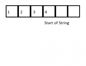
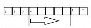
Before continuing, we should probably update our understanding of the client packet’s current possible layout being sent to the named pipe server. Earlier in this blog post we understood some of the first few elements within the client packet; however, now we understand a potential string up to0xFEbytes in length may be present starting at offset0x04into our client packet. A visual representation can be seen in the image below.
Figure 38 – Start of string within client packetDigging into sub_12E0 – Client Packet String > 5 bytes in Length
Starting at address offset
0x159F, another check is present where the total number of bytes read (the return value fromstrnlen()) must be greater than0x05bytes, otherwise code execution will divert into an error, and the application will terminate.
At this moment, we have identified another boundary on the type of packet that the named pipe server expects to receive from a client. A visual representation of this new boundary can be seen in the image below.
Figure 39 – Min String Length BoundaryDigging into sub_12E0 – Copying String from client packet to ‘ourStruct’ structures first member field
Upon a string that is greater than
0x05bytes being provided within our client packet, the next code block executed I at address offset0x01633. This code block is responsible for some interesting behavior such as:
- Copying client packet string into first member field of
ourStruct - Updating two other fields within the
ourStructstructure
This is important because, as mentioned earlier, context is extremely valuable when it comes to reversing undocumented structures and their associated member fields. Being able to see HOW the member fields are utilized and operated on provided powerful insight during our static analysis.
The associated assembly within this code block at address offset 0x1633, can be seen in the table below.
Memcpy() & Updating ‘outStruct’ member fields .text:0000000000001633 loc_1633: ; CODE XREF: sub_12E0+2C3↑j .text:0000000000001633 mov rdx, [rsi] .text:0000000000001636 mov r8, rbx ; Size .text:0000000000001639 add rdx, 3 ; Src .text:000000000000163D mov rcx, rdi ; void * .text:0000000000001640 call memcpy .text:0000000000001645 mov [rdi+100h], ebx .text:000000000000164B mov [rdi+104h], r14d .text:0000000000001652 jmp loc_1739Quickly identifying the
memcpy()call, we can see that the destination argument, is the first member within the ‘ourStruct’ structure. The source argument, is the string starting at element four into the client packet (local vector object) and finally the size argument is the return value from the previousstrnlen()function call, executed at address offset0x158D.Digging into sub_12E0 – Verifying first member field of ‘ourStruct’ is of a char array data type
Circling back to reversing structures, earlier in this blog post, we identified that the first member field within the ‘ourStruct’ structure was possibly an array of 255 bytes. This observation occurred when reviewing a
memset()function call, executed at address offset0x1364. By observing the assembly around locations where the first member field within the ‘ourStruct’ structure is operated on, we can understand the specific data type this member field represents.Starting at address offset
0x158D, astrnlen()function call is made where a string within the client packet is read, where the max amount of bytes that will be read is set to0xFE. The next clue that provides us with some more information is at address offset0x1364. At this address, the first member field within our ‘ourStruct’ structure is used as a destination buffer of amemcpy()function call where the max amount of bytes that can by copied, is equal or less than the total size of the first member fields byte array.With this information, we can conclude with an educated decision that the first member field is a byte array that holds the client’s string located at the fourth element within the client packet (local vector object). Using this information, we can rename the first member field to a more descriptive name, such as
clientPackStringValuefor example. An updated ‘ourStruct’ structure can be seen in the image below.
Figure 40 – First Member Field Name UpdatedDigging into sub_12E0 – Updating two Integer Member Fields within ‘ourStruct’
After updating the first member field within ‘ourStruct’, immediately after the ‘memcpy()’ function call, executed at address offset
0x1640, two other member fields within ‘ourStruct’ are also operated on. The first member field is at offset0x100and the second member field is at offset0x104. These two fields appear to both be integers becauser14isnull, because of thexorinstruction executed at address offset0x131F, and theEBXregister is an integer ofsize_ttype and is the return value from thestrnlen()function call at address offset0x158D. The assembly relating to this functionality can be seen in the table below.Memcpy() & Updating ‘outStruct’ member fields .text:0000000000001633 loc_1633: ; CODE XREF: sub_12E0+2C3↑j .text:0000000000001633 mov rdx, [rsi] .text:0000000000001636 mov r8, rbx ; Size .text:0000000000001639 add rdx, 3 ; Src .text:000000000000163D mov rcx, rdi ; void * .text:0000000000001640 call memcpy .text:0000000000001645 mov [rdi+100h], ebx .text:000000000000164B mov [rdi+104h], r14d .text:0000000000001652 jmp loc_1739With the knowledge that
EBX, holds the total number of bytes within the string element of our client packet (local vector object), we can rename the member field at this offset toclientPacketStringLength. The updated structure can be seen in the image below.
Figure 41 – Second Member Field Name UpdatedLooking into the second member field at offset
0x104, since the value assigned isnulland we have very little context, we could rename this member field to possibly,potentailReturnValue. However, if we take a second and look at other code paths within thesub_12E0function where this member field is used, we will identify an interesting pattern. Reviewing the image below, each code block where the member field at offset0x104is referenced is highlighted in a box.
Figure 42 – All References to ‘ourStruct’ member field at offset ‘0x104’dReviewing the image above, it is apparent that eight code blocks are present where the member field at offset
0x104of ‘ourStruct’ is referenced. Each of these code blocks also immediately returns into the function epilogue before returning code execution to the caller function. With this information, the third member field, at offset0x104, within ‘ourStruct’ could actually be a possible return value for thesub_12E0function. At each code block, a different value ranging from0x00to0x08is assigned, except for two code blocks where the value isnull(passed via r14d).Understanding that the return value of this function could be stored within the member field for the ‘ourStruct’ structure, it is possible that further in the application life cycle, this value may be checked for a specific return value. For now, we are going to assign the name
clientPacketStringRetValue, until we can understand further how this member field is utilized. An updated ‘ourStruct’ structure can be seen in the image below.
Figure 43 – Third Member Field Name UpdatedAfter modification of these last two member fields, code execution diverts to the function epilogue, and the local structure referenced within
RDIis passed toRAX(the function return value), and the function returns to the caller (sub_2D90).Reversing Structures – Returning to sub_2D90
Upon returning to
sub_2D90, the return value (stored within RAX) is immediately used as the source buffer during amemcpy()function call. The destination argument is another local variable calledpszPath, and the total number of bytes copied is0x624. This behavior is seen in the table below.Copying ‘ourStruct’ returned from ‘sub_12E0’ into ‘pszPath’ .text:0000000000003843 lea rcx, [rsp+0CA0h+var_C80] ; void * .text:0000000000003848 mov rdx, rdi ; clientPktVector argument #1 .text:000000000000384B call sub_12E0 ; our call to getName() .text:0000000000003850 lea rcx, [rbp+0BA0h+pszPath] ; void * .text:0000000000003857 mov rdx, rax ; Src .text:000000000000385A mov r8d, 624h ; Size .text:0000000000003860 call memcpy .text:0000000000003865 mov rcx, cs:?cout@std@@3V?$basic_ostream@DU?$char_traits@D@std@@@1@A ; a1 .text:000000000000386C cmp [rbp+0BA0h+var_54C], r14d .text:0000000000003873 jnz loc_3957Reviewing the behavior of the ‘memcpy()’ function call, it is apparent that
pszPathis actually a direct copy of thevar_C80local structure that we have been modifying throughout this post. By modifying thepszPathlocal variable and assigning it the value ofourStruct, all the local references where anoffsetfrompszPathis updated accordingly using the member fields within the ‘ourStruct’ structure. An example of this behavior can be seen in the table below.Updated <code>pszPath</code> local variable .text:000000000000384B call sub_12E0 ; our call to getName() .text:0000000000003850 lea rcx, [rbp+0BA0h+pszPath] ; void * .text:0000000000003857 mov rdx, rax ; Src .text:000000000000385A mov r8d, 624h ; Size .text:0000000000003860 call memcpy .text:0000000000003865 mov rcx, cs:std::ostream std::cout ; a1 .text:000000000000386C cmp [rbp+0BA0h+pszPath.clientPacketStringRetValue], r14d .text:0000000000003873 jnz loc_3957Reviewing the newly updated
pszPathstructure within the table above, it is apparent that at address offset0x386C, a comparison is made between theclientPacketStringRetValueand the value ther14dregister currently holds. If these two do not equal each other, code execution diverts to an error, and the application terminates. However, if they do equal each other, code execution diverts to address offset0x3879.At this moment,
r14dis equal tonull, via axorinstruction executed at address offset0x2DCC. TheclientPacketStringRetValuestructure member holds a value of0x00at this moment, causing this check to fail.Reversing Structures – Entering next code block – 0x3879
This code block is extremely relatable to the code block at address offset
0x37FA. Nearly identical code exists within the two code blocks, as seen in the table below.
Figure 43 – Third Member Field Name UpdatedComparing the two code blocks, we see direct usage of
var_C80being passed via RCX, and immediately after returning fromsub_[1760/12E0]function, amemcpy()function call is executed where the structure returned viaRAXis copied intopszPathstructure.Another similar note is that at the end of the code, a comparison is made where in
0x3879code block, thearray3member field is utilized instead ofclientPacketStringRetValuewas within the0x37FAcode block (this is a hint as to which data typearray3represents).
Full reversing of thesub_1760function is out of scope for this blog post; however, avid readers are encouraged to use the techniques covered through this blog post so far to try reversing the entire function. Modification to the ‘ourStruct’ structure will be encouraged as the behavior betweensub_1760andsub_12E0are quite similar in nature!At the end of the code block at address offset
0x3879, a comparison is made where a potential return value stored withinarray3is checked againstr14dand if these two values are not equal, then code execution diverts, and the application terminates via an error. However, if the two values are equal, then code execution diverts to the next code block, starting at address offset0x38CE.Reversing Structures – Entering the ‘WriteFile()’ function
Upon entering the code block at address offset
0x38CE, a function call is made where the ‘pszPath’ structure is passed via theRCXregister. It is important to note that at this moment, ‘pszPath’ holds the same information as ‘var_C80’ which both local structures are treated as an ‘ourStruct’ structure. This structure was created manually through the ‘Static Analysis – Reversing Structures sections of this blog post.An example of the assembly instructions within the code block at address offset
0x38CEcan be found in the table below.Entering into the ‘WriteFile()’ function .text:00000000000038CE lea rdx, aServerGetvalue ; "t[+] Server: getValue() function succe"... .text:00000000000038D5 call print_ .text:00000000000038DA mov rcx, rax .text:00000000000038DD lea rdx, std::endl<char,std::char_traits<char>>(std::ostream &) .text:00000000000038E4 call cs:std::ostream::operator<<(std::ostream & (*)(std::ostream &)) .text:00000000000038EA lea rcx, [rbp+0BA0h+pszPath] .text:00000000000038F1 call sub_1BD0 .text:00000000000038F6 lea rdx, aServerWriteFil ; "nt[+] Server: write_file() function s"... .text:00000000000038FD mov rcx, cs:std::ostream std::cout ; a1 .text:0000000000003904 cmp dword ptr [rbp+0BA0h+pszPath.array8], r14d .text:000000000000390B jz short loc_3914The function
sub_1BD0()is the actual function responsible for privileged operations (in this event, writing files using data obtained from parsing the incoming client packet) and is the example code path that we will exploit in this blog post.Exploitation – Introduction
In this blog post, we covered the following information:
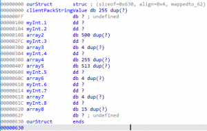
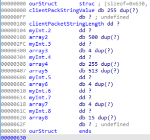
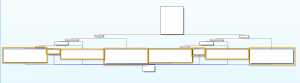
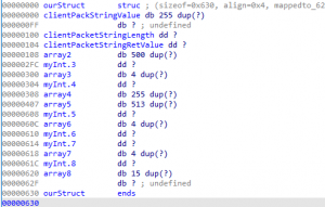
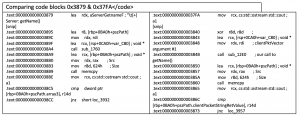
- How to approach auditing an application using static analysis
- How to understand code flow within an application
- Understanding compiler optimizations
- Understanding how to identify attacker input and trace their usage within an application
- Reviewed reversing usage of Vector objects.
- Reviewed reversing undocumented structures
All these topics lead into the second half of this blog post surrounding exploitation.
Overview of the WriteFile() function (sub_1BD0)
Reviewing sub_1BD0, the first task to perform is reviewing the graph view image of the function, using the same techniques as discussed earlier within this blog post. The graph view image overview can be seen in the image below.
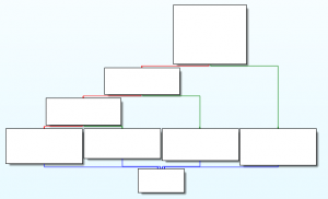
Figure 44 – sub_1BD0 overview
Reviewing the image above, it is apparent that more code exists within the left side. The right side could either be potential error paths or paths that do not require an initial setup of arguments before calling into potential callee functions. In either case, by reviewing the output of the WinGraph32 – Xref from window, we will be presented with the following information:
- How to approach auditing an application using static analysis
- CreateFile
- WriteFile
- CloseHandle
Since the sub_1BD0 function directly calls into these functions, it appears that functionality relating file operations are present within this function. By reversing this function, we will see if the incoming client packet data extracted from the local vector object, stored within pszPath structure within sub_2D90, is utilized as arguments to these privileged file operation functions.
Reversing sub_1BD0 – First Code Block
Upon entering sub_1BD0 and skipping the function prologue, the first interesting instruction executed is at address offset 0x1BE6 as seen in the table below.
NOPE
At address offsets 0x1BE6, 0x1BF0, and 0x1BF8 the xor instruction is executed.
0x1BE6– Used to initialize arguments to two different functions- At address offset
0x01BF3, thehTemplateFileargument is initialized to null-
- Used as an argument to
CreateFileA()
- Used as an argument to
-
- At address offset
0x1C13, theNumberOfBytesWrittenargument is initialized to null- Used as an argument to
WriteFile()
- Used as an argument to
- At address offset
0x1BFO– Used to initialize thelpSecurityAttributesargument to theCreateFileA()function0x1BF8– Used to initialize thedwShareModeargument to theCreateFileA()function
Noticing that a CreateFileA() function is being executed, we are interested in understanding where the lpFileName argument is coming from. Starting at the reference made at address offset 0x1C10 we notice that the value the RCX register holds is copied into the RBX register. Knowing that the calling conventions for 64-bit binaries on Windows utilize the first argument passed via RCX, we can trace any assignments made to this register.
Tracing RCX assignments within this first code block upon entering sub_1BD0, leads to discovering no assignments being executed. This means that the first argument, lpFileName (passed via RCX), is an argument to the sub_1BD0 function. By cross-referencing locations where the sub_1BDO function is called, we will be able to identify what the value of RCX is at the time sub_1BDO is called. The associated cross reference can be seen in the image below.
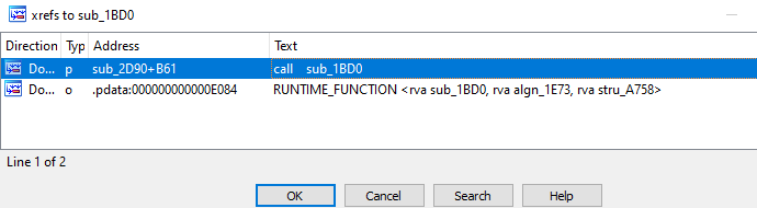
Figure 45 – Cross Refencing usage of
sub_1BD0Reviewing the image above depicting the cross-references to sub_1BD0 function, it appears only a single reference is identified, and that is at offset 0xB61 into the sub_2D90 function. By navigating to this location, we discover that the first member of the pszPath structure is passed. This can be seen in the image below.
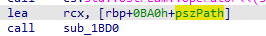
Figure 46 – Identifying the Argument passed to
sub_1BD0Noticing that the pszPath local structure is being passed as the only argument to sub_1BD0 this means that the first argument passed to the function, CreateFileA(), utilizes the string at the fourth element of our client packet (local vector object) which has a max size of 0xFE. Navigating back to the CreateFileA() function call within sub_1BD0 at address offset 0x1C17, we will continue our analysis.
The CreateFileA() function returns a handle, and a check is performed against the handle to make sure that CreateFileA() is executed successfully. If CreateFileA() failed to execute accurately, then the return value is -1 (0xFFFFFFFF), which corresponds to the constant INVALID_HANDLE_VALUE within the handleapi.h source file.
Upon obtaining a handle to the file object relating to the attacker provided string, code execution diverts to the next code block at address offset 0x1C31. Within this code block, a call to WriteFile() is executed where the handle object passed via the RDI register, which corresponds to the handle object returned from the previous CreateFileA() function.
Reviewing the arguments that are passed to WriteFile() and their associated values can seen in the list below:
- hFile – Assigned via
RDIwhich is the return value fromCreateFileA() - lpBuffer – Is a byte array member field within the ‘ourStruct’ structure at offset
0x108- This structure should have been reversed within the
sub_1760
- This structure should have been reversed within the
- Understanding how to identify attacker input and trace their usage within an application
- nNumberOfBytesToWrite – Is an integer member field within the ‘ourStruct’ structure at offset
0x2FC - lpNumberOfBytesWritten – This is null and updated before returning from
WriteFile() - lpOverlapped – This is null and is not utilized during this function call
Reviewing the information in the above list, it is apparent that two more values from our client packet (local vector object) are being utilized during the call to WriteFile(). The most important arguments in this care are lpBuffer and nNumberOfBytesToWrite (both member fields were left as an assignment for the reader to reverse earlier in this blog post). The lpBuffer argument is the exact data that shall be written to the file referenced by the handle object, and the nNumberOfBytesToWrite tells the function WriteFile(), how many bytes to write from the provided buffer within the lpBuffer argument.
Exploitation – Why is this vulnerable?
The call to WriteFIle() is vulnerable because no checks are made by the privileged system service (in this event the named pipe server) to prevent unauthorized processes from sending arbitrary data to cause the creation of any file anywhere on the disk where normal users may not have adequate permissions to write normally.
Since attackers with fewer privileges can control the complete filename (including the extension) and file data, exploitation should be straight forward since attackers can write potential raw binaries or maybe create a malicious configuration file that normally the attacker would not be able to create.
If the developers intend for the privileged system service to remain accessible by less privileged processes, it is important that they properly implement checks on the incoming data to prevent these types of logic-based vulnerabilities. Some examples of these checks can be seen in the list below.
- Verifying allowed folders to create files within
- Controlling the extension of the newly created file
- Verifying the format of the incoming file data to match a specific format before writing to disk
These are just examples and is not an exhaustive list of every possible solution.
Exploitation – Bringing Everything Together
Utilizing all the knowledge we have gained so far from reversing this custom named pipe server. We can utilize the information covered within the previous three blog posts to understand how to create a named pipe client that can send a malicious packet to the named pipe server to create a file in a restricted folder such as C:WindowsSystem32. A list of the blog posts can be seen below:
- Part I: The Fundamentals of Windows Named Pipes
- Part II: Analysis of a Vulnerable Microsoft Windows Named Pipe Application
- Part III: Reversing & Exploiting Custom Windows Named Pipe Servers
Conclusion
This blog post covered quite a bit of material to provide readers with a step-by-step approach to perform static analysis while reversing custom named pipe servers. Many different topics were either covered in-depth or lightly touched on. Some of these topics include vector objects, reversing structures, understanding compiler optimizations, understanding how certain data types are operated on within assembly, how to reverse custom protocols, how to trace attacker input through a binary, and the list goes on.
The previous three blog posts were designed to provide an overall high-level view of how to approach named pipe servers specifically; however, we created this post with the idea that a reader can take the skills learned here and apply them to any binary they encounter in the future. It is important to understand that this post is not a complete, exhaustive reference of everything. Many topics are still left uncovered within this post; however, this post should act as a great entry into building a foundation on which your skills can be built even further.
VerSprite Security Research Team
Maintain awareness regarding unknown threats to your products, technologies, and enterprise networks. Organizations that are willing to take the next step in proactively securing their flagship product or environment can leverage our zero-day vulnerability research offering. Our subscription-based capability provides your organization with immediate access to zero-day vulnerabilities affecting products and software. Learn More →